Stacker
(Source: Stacker.doc Rev. 1.9 2016-03-10)
©

Büro für Datentechnik GmbH
D-35418 Buseck
Germany
Stacker
(Source: Stacker.doc Rev. 1.9 2016-03-10)
©
Büro für Datentechnik GmbH
D-35418 Buseck
Germany
4.1.1 Stack Components Configuration Example
4.1.1.1 Adding Stack Components
4.1.1.2 Configuration of Stack Components
4.3 Stacker Menus and related Windows
4.3.1.5 Offline Edit Config File …
4.3.2.4 Define Replacement Table…
4.3.5.2 AIDA System Settings …
5 CAN Communication via CanEasy IPC
6 Configuration of Beyond Compare 3 to compare *.aida-cfg files as text files
7.2 The AIDA Interface Driver Concept
7.3 The Structure of AIDA Drivers
7.4 The API of the AIDA Interface Drivers
|
Date |
Author |
Rev. |
Description |
|
2013-02-01 |
Karl H. Damm |
1.1 |
First creation as printable document |
|
2013-05-17 |
Michael Schreiber |
1.4 |
Completion |
|
2013-06-21 |
Karl H. Damm |
|
Chapter 4.3.5.2: AIDA System Setting details specified Chapter 4.3.5.3 and 4.3.5.4: CanEasy/BSKD7 installation specific info added Chapter 5 "CAN Communication via CanEasy IPC" added Chapter 7: Correction: BDiag.component instead of BSKD.component |
|
2013-09-27 |
Michael Schreiber Karl H. Damm |
|
Chapter 4.4.1 "Stack Manager Window": Update: new button "Assign" added Various figures: screenshots of Stack Manager Window updated |
|
2013-11-05 |
Karl H. Damm |
1.6 |
Chapter 6 " Configuration of Beyond Compare 3 to compare *.aida-cfg files as text files" added |
|
2014-05-22 |
Hans Schmidts |
1.7 |
Hyperlinks updated |
|
2014-06-13 |
Hans Schmidts |
1.8 |
|
|
2016-03-10 |
Hans Schmidts |
1.9 |
"Symbol" chars replaced (for Firefox etc.) |
|
2016-10-13 |
Andre Decher |
1.10 |
Chapter 5 "CAN Communication via CanEasy IPC" Update: display a warning message only if CanEasy.exe process cannot be found |
The AIDA Stacker is part of the AIDA tool set as well as of the CanEasy/BSKD7 tool set. It combines two functions:
1. Configuration and parameterization of AIDA Stacks.
The AIDA Stacker allows the configuration and parameterization of AIDA Stacks. These stacks define the communication structure and are fundamental to other AIDA tools. An AIDA stack is built of AIDA Stack Components, for details see in particular the chapters Basic Configuration and Stack Manager. The AIDA Components are described in a separate document.
2. Monitoring communication and sending messages.
The AIDA Stacker is also a simple receiver and transmitter application. It listens to stack communication an shows the received messages in a log window or saves received data to a log file. There are filter options to restrict the incoming messages to be logged depending on stack levels, event types etc. For details on monitoring and logging see especially the chapters Control Panel and ID Filter….
The AIDA Stacker also allows to send spontaneous messages as well as
defining cyclic messages. Details can be found in the chapters Control Panel and Cyclic Events….
The AIDA tool set (as well as parts of the CanEasy/BSKD7 tool set) is based on pre-configured communication stacks, that are assembled using the AIDA Stacker. These stacks are stored in the form of a *.aida-cfg file. These files define the basis of communication for BSKD, AIDA Communicator, AIDA Tracer and other AIDA applications.
These stacks consist of stack components that are stacked on each other. Most components have parameters to configure the parameter behavior. The AIDA Stacker allows creating new stack configuration files as well as loading and modifying existing stack configuration files.
In the following example the typical workflow for the creation of a simple CAN communication stack (11bit identifier length, 100 kbps) is demonstrated:
Start AIDA_Stacker.exe and choose menu item Files – Create New Stack as shown in the following figure:
Figure 1: Create New Stack
AIDA stacks consist of stack components, that represent the communication layers. AIDA Stacker provides the Stack Manager Window to add these components together. Select menu item Files – Create New Stack to open the stack manager window.
Figure 2: Stack Manager
Figure 3: Add Component
The Stack manager window is the central place to add and remove components to stacks. When adding components, the order of the components is ‘top-down’, that means that higher layers are on the top and lower levels (closer to the hardware) are on the bottom. The components have to be added in top-down sequence. For details of the stack concept see the advanced chapter AIDA Driver-Stacks.
For this example, the stack will consist of two components:
• at first the higher (top, here Filter) stack component (communication layers) is added:
• the last stack component (here CAN) represents the physical layer.
AIDA Communicator and AIDA Tracer typically requires a filter component, which is added with the stack manager Add button. The following dialog appears after pressing the Add button.
Figure 4: Choose Filter Component
Select Filter and press button Add Selected Component.
As next and last component add the CAN component by selecting CAN and pressing the Add Selected Component button again. Close the dialog by pressing the Cancel button.
Every stack component has a set of parameters. When a component is added to the stack, these parameters are set to their default values. Before the new stack can be used, the stack components parameters have to be adjusted.
The default settings of the Filter component allow reception of all communication messages. (For detailed information on filter configuration refer to AIDA Component descriptions.)
To configure the CAN component, select CAN in the Stack list and press Configure:
Figure 5: Stack Manager
This will open the parameter dialog for the CAN component:
Figure 6: CAN Component Parameterization
Hint: To change the configuration settings of the CAN component, the component must be disconnected first by setting the ChannelMask to $0. This is the default setting of a newly added CAN component.
Now set stack parameter Bitrate to 100000.
Figure 7: Set Bitrate
"11bit CAN identifier length" is set by parameters AcceptanceCode and AcceptanceMask equal $0 (see comment in corresponding stack dialog).
The last step is the configuration of the ChannelMask corresponding to the attached CAN interface respectively the chosen CAN driver. Mask different from $0 refer to actual CAN channels, selecting them will activate CAN interface immediately. Hint: Parameter values that enable the communication interface are shown with a symbol right to the value as shown in Figure 8: Setting Parameter ChannelMask. As soon as the channel mask is set to the right value, the Stacker log window in the AIDA Stacker main window shows possible communication data received on the CAN bus.
Figure 8: Setting Parameter ChannelMask
To save the sample stack configuration select Files – Save Stack as... and chose file name C:\test.aida-cfg.
The AIDA Stacker main window is split into two sections. The upper section is the control panel; the lower section contains the log window/panel.
The layout depends on the selected user mode, which is either expert or basic mode.
Figure 9: AIDA Stacker main window – Expert Mode
In basic mode the advanced controls are hidden:
Figure 10: AIDA Stacker main window – Basic Mode
The following figure shows the control panel in the expert mode:
Figure 11: AIDA Stacker main window: control panel
Stack Status group:
![]() Stack Status shows the status
of the current stack configuration
Stack Status shows the status
of the current stack configuration
• Complete: is set when the stack is complete and can be set to online state
• StackOnline: is set when the stack is online, that means the hardware driver component has opened a communication port
• StackForcedOffline: is set when the stack is forced offline by the application
• InvalidStatus should normally not be seen by the application.
See also the related AIDA Stacks API documentation for AIDA_dwGetStackStatus.
![]() Set Stack Online / Offline:
Sets an AIDA Stack to online / offline state. The buttons are only available
when a valid stack configuration is ready to run. If the stack configuration is
not complete, the buttons are grayed out. See also the related AIDA Stacks API
documentation for AIDA_boSetStackOnline and AIDA_boSetStackOffline.
Set Stack Online / Offline:
Sets an AIDA Stack to online / offline state. The buttons are only available
when a valid stack configuration is ready to run. If the stack configuration is
not complete, the buttons are grayed out. See also the related AIDA Stacks API
documentation for AIDA_boSetStackOnline and AIDA_boSetStackOffline.
Log File group:
![]() Log File: Shows the path of
the selected log file. Double click on the label to select a log file.
Log File: Shows the path of
the selected log file. Double click on the label to select a log file.
![]() Start / Pause Logging: When a
log file has been selected, the logging to the given file can be started and
paused here. When logging to file is active, the logging can be interrupted and
continued later.
Start / Pause Logging: When a
log file has been selected, the logging to the given file can be started and
paused here. When logging to file is active, the logging can be interrupted and
continued later.
![]() Close Log File: Closes the log
file. This will also release any file locks (i.e. unless the file is released,
it may not be possible to move or rename the log file).
Close Log File: Closes the log
file. This will also release any file locks (i.e. unless the file is released,
it may not be possible to move or rename the log file).
![]() Settings: Open the Settings dialog, see section Settings.
Settings: Open the Settings dialog, see section Settings.
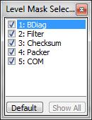
![]() Filter Mask - Level: Selects
the Stack levels that the AIDA Stacker shall log. The value
is a bit mask where bit 1 (counted from zero) stands for Stack level 1, bit 2
stands for Stack level 2, etc. With the arrow button on the right side of the
mask field, a level mask editor dialog pops up.
Filter Mask - Level: Selects
the Stack levels that the AIDA Stacker shall log. The value
is a bit mask where bit 1 (counted from zero) stands for Stack level 1, bit 2
stands for Stack level 2, etc. With the arrow button on the right side of the
mask field, a level mask editor dialog pops up.
Figure 12: Level Mask Selector dialog
In the level mask selector, all stack levels can be enabled or disabled separately by checking the corresponding check box. The Default button unchecks all parameters, corresponding to a mask setting of 0. This setting has a special meaning, as it will output the events for the uppermost level only (i.e. it does not filter out all messages, as the zero suggests). The Show All button enables all levels.
![]() Filter Mask - Event: Select
the event types which the AIDA Stacker shall log. The value is a bit mask where
bit 0 corresponds type 0 (ReceiveData), bit 1 stands for type 1 (TransmitData),
etc. (ReceiveData, TransmitData, TransmitDataDone, Status, Timer). For details
see the AIDA Stacks API documentation for AIDA_tenEventType.
Filter Mask - Event: Select
the event types which the AIDA Stacker shall log. The value is a bit mask where
bit 0 corresponds type 0 (ReceiveData), bit 1 stands for type 1 (TransmitData),
etc. (ReceiveData, TransmitData, TransmitDataDone, Status, Timer). For details
see the AIDA Stacks API documentation for AIDA_tenEventType.
With the arrow button on the right side of the mask field, a level mask editor dialog pops up.
Figure 13: Event Mask Selector dialog
In the event mask selector, all event types can be enabled or disabled separately
by checking the corresponding check box. The None button unchecks all event
types, corresponding to a mask setting of 0.. The Select All button enables all
levels.
Timer Settings:
![]() Timer: Selects the interval
for the uppermost component to generate timer events.
Timer: Selects the interval
for the uppermost component to generate timer events.
Send Data:
![]() Data: This text box allows
editing a sequence of hexadecimal bytes. Press <ENTER> to send an event
with the given data.
Data: This text box allows
editing a sequence of hexadecimal bytes. Press <ENTER> to send an event
with the given data.
![]() SrcID: Set the source ID (low
Dword only) to be used in transmitted events.
SrcID: Set the source ID (low
Dword only) to be used in transmitted events.
![]() DstID: Set the destination ID
(low Dword only) to be used in transmitted events.
DstID: Set the destination ID
(low Dword only) to be used in transmitted events.
![]() Data Flags: Set flags for the
data part of transmitted events.
Data Flags: Set flags for the
data part of transmitted events.
![]() Level: Choose the stack level
to which the event shall be transmitted. Leave empty or enter 0 for the top
level (default).
Level: Choose the stack level
to which the event shall be transmitted. Leave empty or enter 0 for the top
level (default).
![]() CStart: Similar to pressing
<ENTER> in the input box Data, but additionally set the flag StartCommu in the event. See the related AIDA Stacks API documentation for AIDA_tstEvent#dwFlags.
CStart: Similar to pressing
<ENTER> in the input box Data, but additionally set the flag StartCommu in the event. See the related AIDA Stacks API documentation for AIDA_tstEvent#dwFlags.
![]() CStop: Similar to pressing
<ENTER> in the input box Data, but additionally set the flag StopCommu in the event. See the related AIDA Stacks API documentation for AIDA_tstEvent#dwFlags.
CStop: Similar to pressing
<ENTER> in the input box Data, but additionally set the flag StopCommu in the event. See the related AIDA Stacks API documentation for AIDA_tstEvent#dwFlags.
![]() Cycle Count: Number of cycles
(0 means infinite).
Cycle Count: Number of cycles
(0 means infinite).
![]() Period [ms]: Cycle time in Milliseconds.
Period [ms]: Cycle time in Milliseconds.
![]() Add: Creates and activates a
new cyclic event using the specified Data, SrcID, DstID, Data Flags, Level, Cycle Count and Period [ms] values. Appends a
corresponding new entry to the table in the Cyclic Events window. See
Add: Creates and activates a
new cyclic event using the specified Data, SrcID, DstID, Data Flags, Level, Cycle Count and Period [ms] values. Appends a
corresponding new entry to the table in the Cyclic Events window. See ![]() .
.
![]() Manage Events: Opens the Cyclic Events window, see
section Cyclic Events….
Manage Events: Opens the Cyclic Events window, see
section Cyclic Events….
![]() Group-Panel Statistics (see also section Show Statistics):
Group-Panel Statistics (see also section Show Statistics):
• Msg Tx:
The number of transmitted AIDA events since the stack has been loaded.
• Msg Rx:
The number of received AIDA events since the stack has been loaded.
• Err Tx:
The number of transmitted AIDA events with any error flags set (but not AIDA_nRecvQueueOverrun) since the stack has been loaded.
• Err Rx:
The number of received AIDA events with any error flags set (but not AIDA_nRecvQueueOverrun) since the stack has been loaded.
• Ovr:
The number of AIDA events with error flag AIDA_nRecvQueueOverrun set, i.e. the number of events lost because a higher component did
not empty the receive queue.
See also section Show Statistics.
In the log window, the received messages are protocolled. It is possible to scroll back in the message buffer, the buffer stores up to 2000 lines.
Figure 14: AIDA Stacker main window: Log panel/window
The components of the log window are:
![]()
![]() : Select absolute (t) or relative (Delta t) time
stamps in the log window. This also affects the log files, when the logging
format is configured to ‘Same as log window’.
: Select absolute (t) or relative (Delta t) time
stamps in the log window. This also affects the log files, when the logging
format is configured to ‘Same as log window’.
![]() Freeze: Freezes the log window
contents. When the window is frozen, the communication still continues; events
received while the window was frozen are stored and are shown after returning
from freeze state.
Freeze: Freezes the log window
contents. When the window is frozen, the communication still continues; events
received while the window was frozen are stored and are shown after returning
from freeze state.
![]() Clear: Clears the trace buffer
and the contents of the log window.
Clear: Clears the trace buffer
and the contents of the log window.
![]() Save: Save trace buffer (the
contents of the log window) to file.
Save: Save trace buffer (the
contents of the log window) to file.
![]() To Clipboard: Copies the log
window contents to the system clipboard.
To Clipboard: Copies the log
window contents to the system clipboard.
The log output is formatted as a table, the columns are as shown in the headline:
1.
Timestamp:
The timestamp for the shown message or event. Depending on the absolute or
relative selection, either the time since the last message/event is shown
(relative), or the absolute time (from Windows PC system timer) is shown.
2.
Cyclic:
When the message was generated by the AIDA Stacker itself using cyclic events,
the message is marked with a dot in this column. For all other messages or
events this column entry remains empty.
3. ID: Event ID that AIDA has assigned to this message/event internally
4.
Level:
Stack level that generated the message. Depending on the filter mask settings
for the levels to be logged, the same message can be multiply shown, as every
stack component, that handles the message and passes it to the next level,
triggers an indication.
5. Type:
The type is one of the following:
• Status
• Stacker message
• ReceiveData
• TransmitData
• TransmitDataDone
6. Source ID and Destination ID as passed from the AIDA component.
Remark: availability of IDs depends on the stack configuration, some components do not generate IDs. In this case, the ID entry shows ‘--------‘.
7.
DF:
See Component documentation on Data Flags
8.
Data:
This column either shows the message text for an event or the contents of the
message received or transmitted as a sequence of hexadecimal bytes. The number
of bytes that are shown per line can be configured in the settings dialog.
Create and configure a new stack configuration or open an existing configuration. In addition you can change the global settings for the AIDA Stacker.
Creates a new empty stack configuration. As every AIDA Stacker application instance only processes one stack configuration at a time, previously active stack configurations are closed. In case of unsaved changes to the previous configuration an option for saving will appear.
Opens a file dialog box to select and load an existing AIDA Stack configuration (*.aida-cfg).
Saves the current AIDA Stack configuration to disk. If a new "unnamed" stack was created and shall be stored the first time, a file dialog window is opened to choose the filename (incl. directory) (*.aida-cfg).
Opens a file dialog window. Choose an existing directory and type a filename to save the current AIDA Stack configuration with a new name (*.aida-cfg).
Opens a file dialog box to select and load an existing AIDA Stack configuration (*.aida-cfg). Details are described in chapter Fehler! Verweisquelle konnte nicht gefunden werden..
Get information on file structure of a stack configuration file.
Opens a file dialog box to select and load a AIDA Stack configuration file (*.aida-cfg). The configuration file is examined by the command line tool dumpconfig.exe, that is part of the AIDA tool distribution. After processing, the result is automatically opened with the default text editor of the Windows system.
Opens the AIDA Stacker Settings window:
Figure 15: AIDA Stacker Settings window (Appearance and Stack)
![]() Main Window Appearance: The Use Expert mode checkbox: In
expert mode, the main window shows the full user interface. If not checked, the
interface is shown in basic mode, with a reduced user interface.
Main Window Appearance: The Use Expert mode checkbox: In
expert mode, the main window shows the full user interface. If not checked, the
interface is shown in basic mode, with a reduced user interface.
![]() Parameter Dialog: The Highlight changeable Params
checkbox: If checked, the listbox entries for parameters that can currently be
changed are drawn with a bold font (in the Parameters listbox in the Component Parameterization
window). On some machines, the AIDA Stacker user interface reacts slow when
this option is selected, in this case the function should be disabled.
Parameter Dialog: The Highlight changeable Params
checkbox: If checked, the listbox entries for parameters that can currently be
changed are drawn with a bold font (in the Parameters listbox in the Component Parameterization
window). On some machines, the AIDA Stacker user interface reacts slow when
this option is selected, in this case the function should be disabled.
![]() Log Window: The Wrapping Position slider and
number input box: Set the number of hexadecimal bytes to be shown in a line
before wrapping to the next line. As changes in the layout will clear the log
window history, the user must confirm the new wrapping position to make the
change effective.
Log Window: The Wrapping Position slider and
number input box: Set the number of hexadecimal bytes to be shown in a line
before wrapping to the next line. As changes in the layout will clear the log
window history, the user must confirm the new wrapping position to make the
change effective.
![]() The Log Window Color panel: Set
text color and background color of the log window.
The Log Window Color panel: Set
text color and background color of the log window.
![]() The
Restore Defaults checkbox: Load
default values when restoring a Stack from a Stack configuration file (*.aida-cfg),
i.e. no replacement of parameter values with corresponding environment variable
exists.
The
Restore Defaults checkbox: Load
default values when restoring a Stack from a Stack configuration file (*.aida-cfg),
i.e. no replacement of parameter values with corresponding environment variable
exists.
![]() The Use Remote Environment checkbox: Configure usage of the remote environment when restoring
a Stack which contains a NETClient Component.
The Use Remote Environment checkbox: Configure usage of the remote environment when restoring
a Stack which contains a NETClient Component.
![]() The Use managed ID mode: When
checked, managed IDs are forcibly used while loading a new Stack.
The Use managed ID mode: When
checked, managed IDs are forcibly used while loading a new Stack.
![]() Create/Restore Offline: If
checked, the stack is created offline. This allows to load or edit the stack
even when actual hardware components (e.g. CAN adapter) are not available on
the PC.
Create/Restore Offline: If
checked, the stack is created offline. This allows to load or edit the stack
even when actual hardware components (e.g. CAN adapter) are not available on
the PC.
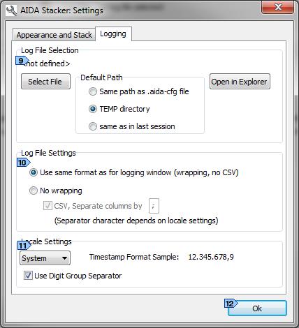
Figure 16: AIDA Stacker Settings window (Logging)
![]() Use as default path: This
setting selects the default path that is used when AIDA Stacker suggests a file
name and path for storage of log files. Available options are:
Use as default path: This
setting selects the default path that is used when AIDA Stacker suggests a file
name and path for storage of log files. Available options are:
• Same path as .aida-cfg file
• TEMP directory
The path is read from the environment variable ‘TEMP’.
With the Open in Explorer button, the folder to contain the log files is opened in a new explorer window.
![]() Log File Settings:
Log File Settings:
• Use same format as for log window
(wrapping, no CSV)
The log file uses the same format as the log window; lines are wrapped
• No wrapping (CSV): The log file uses one line per event, data is not wrapped.
![]() The Locale Settings and the Use Digit Group Separator
checkbox:
The Locale Settings and the Use Digit Group Separator
checkbox:
Configure the format of numeric values in the log window:
• System: Use the user’s settings.
• German: Always use German format (e.g. 123.456.789,012345 or 123456789,012345, depending on the value of the Use Digit Group Separator checkbox)
• English: Always use US format (e.g. 123,456,789.012345 or 123456789.012345, depending on the value of the Use Digit Group Separator checkbox)
![]() Closes the window (same as the
close button ‘X’ in the window’s title bar).
Closes the window (same as the
close button ‘X’ in the window’s title bar).
Terminates the AIDA Stacker application instance. In the case of unsaved changes, a save dialog appears.
Configuration of the stack and parameterization of its contained stack components and plugins.
Opens the Statistics window (non-modal):
Figure 17: Statistics window
The Statistics window shows several sets of information about transmitted and received AIDA events and user data bytes as well as (if supported by the corresponding components) information about the average loads and peak loads.
It lists the following 5 operating modes for each component in the current Stack:
![]() Normal operation: Shows the
statistics data for normal operation. The statistics data will be updated
automatically by the AIDA library without intervention of the components.
Normal operation: Shows the
statistics data for normal operation. The statistics data will be updated
automatically by the AIDA library without intervention of the components.
![]() Emergency operation: Shows the
statistics data for "emergency" operation. The exact meaning depends
on the component for which the data is retrieved, e. g. the CAN component
defines single wire CAN as emergency operation. If a component sets the
corresponding warning flags the information will be updated automatically,
otherwise the component has to update the information itself.
Emergency operation: Shows the
statistics data for "emergency" operation. The exact meaning depends
on the component for which the data is retrieved, e. g. the CAN component
defines single wire CAN as emergency operation. If a component sets the
corresponding warning flags the information will be updated automatically,
otherwise the component has to update the information itself.
![]() Errors: Shows the statistics
data for operations in case of errors. The exact meaning depends on the
component for which the data is retrieved, e. g. the CAN component defines
error frames as error operations but will only count the frames and will not calculate
the bus load in this case. If a component sets the corresponding error flags
the information will be updated automatically, otherwise the component has to
update the information itself.
Errors: Shows the statistics
data for operations in case of errors. The exact meaning depends on the
component for which the data is retrieved, e. g. the CAN component defines
error frames as error operations but will only count the frames and will not calculate
the bus load in this case. If a component sets the corresponding error flags
the information will be updated automatically, otherwise the component has to
update the information itself.
![]() Average load: Shows the
average load of the transport media in units of 0.1%. Note that this
information cannot be generated automatically but must be set up by the
corresponding component for which the statistics data is retrieved. Currently
only the Vector CAN component calculates the average load.
Average load: Shows the
average load of the transport media in units of 0.1%. Note that this
information cannot be generated automatically but must be set up by the
corresponding component for which the statistics data is retrieved. Currently
only the Vector CAN component calculates the average load.
![]() Peak load: Shows the peak load
of the transport media in units of 0.1%. Note that this information will only
be available if the component updates the Average load statistics data.
Peak load: Shows the peak load
of the transport media in units of 0.1%. Note that this information will only
be available if the component updates the Average load statistics data.
The Statistics window contains 2 buttons:
![]() Clear: Clears all statistics
information for all stack levels.
Clear: Clears all statistics
information for all stack levels.
![]() Done: Closes the window (same
as the close button ‘X’ in the window’s title bar).
Done: Closes the window (same
as the close button ‘X’ in the window’s title bar).
Each set of transmit and receive data for a given operating mode contains the following information:
• TX events: The number of transmitted AIDA events since the statistics information last has been cleared.
• TX bytes: The number of transmitted user data bytes since the statistics information last has been cleared.
• RX events: The number of received AIDA events since the statistics information last has been cleared.
• RX bytes: The number of received user data bytes since the statistics information last has been cleared.
See also the related AIDA Stacks API documentation for AIDA_tstStatistics and AIDA_tstStatisticsSet.
Opens the Stack Manager window.
The stack manager is described in chapter Stack Manager.
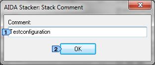
Opens the Stack Comment window:
Figure 18: AIDA Stacker "Stack Comment" window
Every stack can have a comment attached that can hold up to 255 characters. It allows storing remarks on the stack and has no effect on the stack communication.
The stack comment windows fields are:
![]() Text input box Comment: the comment is part
of the Stack configuration file and can be edited. Changes are applied
immediately.
Text input box Comment: the comment is part
of the Stack configuration file and can be edited. Changes are applied
immediately.
![]() Button OK: Closes the window (same as
the close button ‘X’ in the window’s title bar).
Button OK: Closes the window (same as
the close button ‘X’ in the window’s title bar).
Opens the Replacement table window. The replacement handling is explained in chapter Replacement Handling.
Opens the Cyclic Events window. This windows lists all cyclic messages that are defined for the current stack configuration. The details on cyclic events are described in chapter Cyclic Events.
Configuration of a background log file and saving of the current trace buffer to a log file can be done here. A corresponding ID filter list can be configured and applied.
Opens a file dialog to select the file name that shall hold the logged data. When the dialog opens, the name is already preset with the stack’s name followed by the date and time (e.g. SampleStack_20130201_1447.log). The path is preset too, it is either the directory where the stack configuration file is saved, the TEMP directory or the position where the last log file was written to (see settings dialog). Alternatively this dialog can be accessed by double clicking the Log file name in the control area of the main window. The menu is not available unless a stack is loaded or configured.
All messages are either stored in Microsoft Excel compatible CSV format (comma separated value) or alternatively in the same format as used in the log window. Despite of its name, the comma separated values format do not always use commas to separate the columns. When the format of the timestamps already contains commas, the separator character is automatically changed into a semicolon.
The format can be configured within the Settings window (section Log File Settings), which is accessible via menu entry Files – Settings… or main window Settings button.
The following examples show the log file output:
1. Same format as log window
TimeStamp C ID Level Type SrcID DstID DF Data
------------------------------------------------------------------------------------------------------------------------------
23.095,0ms 0001001C 1 TransmitData --------- --------- -- 11 22 33
0,0ms 0001001C 1 Status RestartRXTimeoutStatus: 75,0
RestartTXTimeoutStatus: 75,0
25,0ms 0001001C 1 ReceiveData --------- --------- -- Flags: $00820000 (E:Recv, E:Timeout)
0,0ms 0001001C 1 TransmitDataDone --------- --------- -- 11 22 33
166,0ms 0001001E 1 TransmitData --------- --------- -- 11 22 33
0,0ms 0001001E 1 Status RestartRXTimeoutStatus: 75,0
RestartTXTimeoutStatus: 75,0
25,0ms 0001001E 1 ReceiveData --------- --------- -- Flags: $00820000 (E:Recv, E:Timeout)
0,0ms 0001001E 1 TransmitDataDone --------- --------- -- 11 22 33
151,0ms 00010020 1 TransmitData --------- --------- -- 11 22 33
0,0ms 00010020 1 Status RestartRXTimeoutStatus: 75,0
RestartTXTimeoutStatus: 75,0
25,0ms 00010020 1 ReceiveData --------- --------- -- Flags: $00820000 (E:Recv, E:Timeout)
2. No wrapping, CSV enabled
TimeStamp C ID Level Type SrcID DstID DF Data
------------------------------------------------------------------------------------------------------------------------------
2.916.501.646,0; 177.062,0; 0001002E; 1;TransmitData ;---------;---------; --;;11;22;33
2.916.501.646,0; 0,0; 0001002E; 1;Status ; ; ; ;;RestartRXTimeoutStatus: 75,0 RestartTXTimeoutStatus: 75,0
2.916.501.671,0; 25,0; 0001002E; 1;ReceiveData ;---------;---------; --;Flags: $00820000 (E:Recv, E:Timeout);
2.916.501.671,0; 0,0; 0001002E; 1;TransmitDataDone;---------;---------; --;;11;22;33
2.916.501.822,0; 151,0; 00010030; 1;TransmitData ;---------;---------; --;;11;22;33
2.916.501.822,0; 0,0; 00010030; 1;Status ; ; ; ;;RestartRXTimeoutStatus: 75,0 RestartTXTimeoutStatus: 75,0
2.916.501.847,0; 25,0; 00010030; 1;ReceiveData ;---------;---------; --;Flags: $00820000 (E:Recv, E:Timeout);
2.916.501.847,0; 0,0; 00010030; 1;TransmitDataDone;---------;---------; --;;11;22;33
2.916.501.974,0; 127,0; 00010032; 1;TransmitData ;---------;---------; --;;11;22;33
2.916.501.974,0; 0,0; 00010032; 1;Status ; ; ; ;;RestartRXTimeoutStatus: 75,0 RestartTXTimeoutStatus: 75,0
2.916.501.999,0; 25,0; 00010032; 1;ReceiveData ;---------;---------; --;Flags: $00820000 (E:Recv, E:Timeout);
Opens the ID filter window.
This table configures which events the AIDA Stacker shall show in its log window (and log to a files respectively). Furthermore the assignment of symbolic names to event IDs is possible. Assigning symbolic names is done by entering the event’s stack level, ID and the symbolic name in a table row. When the table terminates with an asterisk ("*") in the stack level column, the AIDA Stacker will show all events no matter whether a symbolic name has been assigned. This table only affects data events.
Figure 19: AIDA Stacker "ID filter" window
The ID filter table has four columns:
![]() Filter number
Filter number
![]() Table column Stack level: the event’s stack
level.
Table column Stack level: the event’s stack
level.
![]() Table column ID: the event’s ID.
Table column ID: the event’s ID.
![]() Table column Name: here you can assign a
symbolic name to the event
Table column Name: here you can assign a
symbolic name to the event
The ID filter window contains 3 buttons:
![]() Clear all: Deletes all
existing table entries.
Clear all: Deletes all
existing table entries.
![]() Apply: Applies the currently
displayed settings.
Apply: Applies the currently
displayed settings.
![]() Done: Closes the ID filter window (same as the
close button ‘X’ in the window’s title bar).
Done: Closes the ID filter window (same as the
close button ‘X’ in the window’s title bar).
Saves the current trace buffer as shown in the log window, with the last 2000 events. The default filename is preset as a combination of the name of the stack configuration file followed by the current date and time e.g.: Test_Stack_20130419_1119.log for Test_Stack.aida-cfg. A message box with the filename and full path is shown when the triggered action is finished successfully.
The buffer contents is stored in the format that is configured in the Settings dialog (section Log File Settings), either in Microsoft Excel compatible CSV format (comma separated value) or alternatively in the same format as used in the log window.
This dynamic menu lists all open secondary, non-modal windows, e.g. the "Settings" window (see section 0), the "ID filter" window (see section 4.3.3.2), the "Statistics" window (see section 4.3.2.1), the "Stack comment" window (see section 4.3.2.3), the "Replacement table" window (see section 4.3.2.4), the "Cyclic events table" window (see section 4.3.2.5), the "Stack Manager" window (see section 4.3.2.2), the various "Component Parameterization" windows (see section 4.3.2.2). Select one of the dynamic menu entries to bring the corresponding window to the front of the desktop.
Gives some help and additional info like AIDA Stacker Revision, license information and additional info …
Shows information about the currently used AIDA interface version and AIDA Stacker revision (and possibly also the AIDA SDK or RTE Platform version) as well as detailed information about the licensed AIDA version, Windows applications, PI modules, Stack Components and Plugins. The license information is extracted from the related license file (*.lic), which must be present within the Stacker executable directory.
Starts the AIDA System Settings Wizard to change the system settings (license file(s), serial port(s), CAN component) for the AIDA installation.
Note: This menu entry is only available when the Stacker is contained in a standard AIDA installation. When the Stacker is installed as part of a CanEasy/BSKD7 installation it is not available.
Opens this documentation (HTML version) in the default web browser or, in case of a CanEasy/BSKD7 installation, in the Microsoft HTML Help Viewer.
Opens the AIDA Stack Components / Plugins and API documentation (HTML version) in the default web browser or, in case of a CanEasy/BSKD7 installation, in the Microsoft HTML Help Viewer.
The Stack Manager is used for
• Adding and removing components
• Accessing the parameter dialogues for all components to adjust parameters
• Rearranging the structure of an existing stack configurations.
Figure 13: Stack Manager window
![]() Stack: A list of the stack
components and their respective level within the current stack. Double click to
open the Component Parameterization
window (see the corresponding description further below) for the selected stack
component.
Stack: A list of the stack
components and their respective level within the current stack. Double click to
open the Component Parameterization
window (see the corresponding description further below) for the selected stack
component.
![]() Add: Pressing this button opens the Add Component dialog window
(see the corresponding description further below), which allows it to select a
stack component, e.g. CAN.component, to add to the top of the stack.
Add: Pressing this button opens the Add Component dialog window
(see the corresponding description further below), which allows it to select a
stack component, e.g. CAN.component, to add to the top of the stack.
![]() Unload: Pressing this button unloads the selected
stack component and all the components below it (with a higher stack level).
These stack components are stored with their frozen parameter settings and are
accessible via the Unloaded
Components listbox, so that they can be added to
the stack again later on.
Unload: Pressing this button unloads the selected
stack component and all the components below it (with a higher stack level).
These stack components are stored with their frozen parameter settings and are
accessible via the Unloaded
Components listbox, so that they can be added to
the stack again later on.
![]() Configure: Pressing this button opens the Component Parameterization
window (see the corresponding description further below) for the selected stack
component.
Configure: Pressing this button opens the Component Parameterization
window (see the corresponding description further below) for the selected stack
component.
![]() Unload Components: A list of
the stack components that have been unloaded from the stack (with frozen
parameter settings).
Unload Components: A list of
the stack components that have been unloaded from the stack (with frozen
parameter settings).
![]() Button Reload: Return the selected
unloaded component back to the top of the stack. When a component is returned
to the stack, the parameters of the component are set to its default values
(i.e. the values in the snapshot are not automatically assigned).
Button Reload: Return the selected
unloaded component back to the top of the stack. When a component is returned
to the stack, the parameters of the component are set to its default values
(i.e. the values in the snapshot are not automatically assigned).
![]() Drop: Removes the selected
stack component from the Unloaded
Components list.
Drop: Removes the selected
stack component from the Unloaded
Components list.
![]() Parameter Snapshots: List of
frozen parameter sets. Every snapshot is identified by its timestamp.
Parameter Snapshots: List of
frozen parameter sets. Every snapshot is identified by its timestamp.
![]() Snapshot: Freeze all the
parameters for components that are currently on the stack.
Snapshot: Freeze all the
parameters for components that are currently on the stack.
![]() Delete: Delete the selected
snapshot from the list of frozen parameter sets.
Delete: Delete the selected
snapshot from the list of frozen parameter sets.
![]() Status: The number of
different parameter values in the current stack configuration in comparison
with the selected snapshot.
Status: The number of
different parameter values in the current stack configuration in comparison
with the selected snapshot.
![]() Button Assign: Assigns the reference
values for all parameters that are different from the value in the snapshot.
Only values that have the attribute ‘ChangeAnytime’ are assigned. When the
Shift key is hold pressed while clicking the button, the limitation on the
attribute is omitted and the function tries to assign all reference values that
are different. Note that attempting to change the values may not be successful
for all values, depending on their changeability property.
Button Assign: Assigns the reference
values for all parameters that are different from the value in the snapshot.
Only values that have the attribute ‘ChangeAnytime’ are assigned. When the
Shift key is hold pressed while clicking the button, the limitation on the
attribute is omitted and the function tries to assign all reference values that
are different. Note that attempting to change the values may not be successful
for all values, depending on their changeability property.
![]() Compare Parameters with Reference: Structured list of all loaded stack components with all
parameters.
Compare Parameters with Reference: Structured list of all loaded stack components with all
parameters.
• Double click to open the Component Parametrization window (see the corresponding description further below) for the selected stack component and parameter.
• Double click with Shift keys hold pressed to try to assign the snapshot reference value.
The parameters are marked with one of these three symbols:
• ![]() : The parameter value is the same as the
corresponding snapshot value
: The parameter value is the same as the
corresponding snapshot value
• ![]() : The parameter value is different from the
value in the snapshot
: The parameter value is different from the
value in the snapshot
• ![]() : The parameter
is not contained in the snapshot
: The parameter
is not contained in the snapshot
![]() Difference-Button
Difference-Button ![]() : Select whether
to show all parameters or only those parameters that have values different to
their corresponding value in the currently selected snapshot.
: Select whether
to show all parameters or only those parameters that have values different to
their corresponding value in the currently selected snapshot.
![]() Toggle-Button Params / Values: Only list
parameter names resp. list parameter names with the assigned values.
Toggle-Button Params / Values: Only list
parameter names resp. list parameter names with the assigned values.
![]() Button Copy List to Clipboard: Copy
the list of stack components and parameters with their assigned values to the
system clipboard.
Button Copy List to Clipboard: Copy
the list of stack components and parameters with their assigned values to the
system clipboard.
![]() Button Ok: Closes the window (same as
the close button ‘X’ in the window’s title bar).
Button Ok: Closes the window (same as
the close button ‘X’ in the window’s title bar).
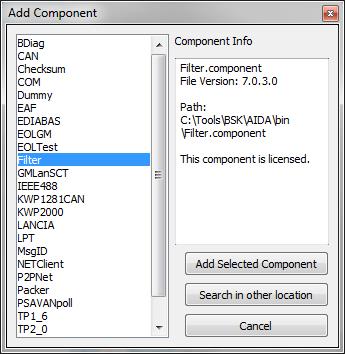
Pressing the button Add in the Stack Manager window opens the Add Component dialog window.
Figure 20: Add Component dialog window
![]() Components: A list of all
components found in the AIDA_Stacker.exe directory.
Components: A list of all
components found in the AIDA_Stacker.exe directory.
![]() Component Info: The stack component’s
file name, filter version and full file system path.
Component Info: The stack component’s
file name, filter version and full file system path.
![]() Add Selected Component: Adds
the selected stack component to the top of the stack.
Add Selected Component: Adds
the selected stack component to the top of the stack.
![]() Search in other location:
Opens a file dialog.
Search in other location:
Opens a file dialog.
![]() Cancel: Closes the dialog
window (same as the close button ‘X’ in the window’s title bar).
Cancel: Closes the dialog
window (same as the close button ‘X’ in the window’s title bar).
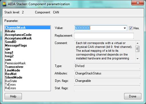
Pressing the button Configure in the Stack Manager window opens the Component Parameterization window.
Figure 21: Component Parameterization window (non-modal), here for CAN
![]() Stack level and Component: The level of the
component within the stack and the stack component’s name, e.g. CAN or Filter.
Stack level and Component: The level of the
component within the stack and the stack component’s name, e.g. CAN or Filter.
![]() Parameter: All parameters of
the stack component. Not all parameters can be changed at any time, e.g. most
parameters require the stack to be set offline before changing is allowed. In
the parameter list, the parameters that are currently allowed to be changed are
shown in bold font.
Parameter: All parameters of
the stack component. Not all parameters can be changed at any time, e.g. most
parameters require the stack to be set offline before changing is allowed. In
the parameter list, the parameters that are currently allowed to be changed are
shown in bold font.
![]() Reference: When a parameter
snapshot was made the reference value is shown here, either in red color when
the snapshot value is different from the current setting, or in green color,
when both values are the same. In case of different values, also an Apply button is visible.
Pressing this button assigns the snapshot reference value to the parameter.
Reference: When a parameter
snapshot was made the reference value is shown here, either in red color when
the snapshot value is different from the current setting, or in green color,
when both values are the same. In case of different values, also an Apply button is visible.
Pressing this button assigns the snapshot reference value to the parameter.
![]() Text input box Value: The value of the
parameter which is selected in the listbox. Most of the parameters are of type Dword or Long, a few are of type Real or String. See also
Text input box Value: The value of the
parameter which is selected in the listbox. Most of the parameters are of type Dword or Long, a few are of type Real or String. See also ![]() .
.
![]() Text
input box Replacement: Optional. The
name of the environment variable containing the replacement value for the
selected parameter. The parameter’s value is replaced with the value given by
the process environment when restoring the stack from the configuration file.
Text
input box Replacement: Optional. The
name of the environment variable containing the replacement value for the
selected parameter. The parameter’s value is replaced with the value given by
the process environment when restoring the stack from the configuration file.
For portable AIDA stack configurations, commonly you would use a project-specific environment variable for workstation-dependent parameters like the CAN Component’s ChannelMask (bit 0 and 1 represent virtual channels if these are supported; physical channels are always located on bit 2 and above) or the NETClient Component’s Server (name of the AIDA stack network server; a DNS name or an IP address). E.g. for a project "DC_W222_KI" you could define corresponding environment. variables "DC_W222_KI_CAN_ChannelMask" and "DC_W222_KI_NETClient_Server" with e.g. values "4" and "BSK-WST-070".
See also the related descriptions in the section Define Replacement Table….
![]() Comment (read-only): A short
description of the selected parameter.
Comment (read-only): A short
description of the selected parameter.
![]() Textbox Type (read-only): The type of
the selected parameter. Possible values are: String, DWord, Long or Real. For details see the related AIDA
Stacks API documentation for AIDA_tenParamType.
Textbox Type (read-only): The type of
the selected parameter. Possible values are: String, DWord, Long or Real. For details see the related AIDA
Stacks API documentation for AIDA_tenParamType.
![]() Attributes (read-only): Attributes
of the selected parameter. Possible values are:
Attributes (read-only): Attributes
of the selected parameter. Possible values are:
• ChangeAnytime
• ChangeOnlyBeforeLoad
• ChangeOnlyAfterLoad
• ChangeOnlyBeforeComplete
• ChangeOnlyAfterComplete
• ChangeOnlyWhen Offline
• ChangeOnlyWhenOnline
• ChangeStackStatus
• ReadOnly
• Change
• OnlyAfter
• CompleteWhenOffline
• ChangeOnlyAfterCompleteWhenOnline
• BroadcastWhenOffline
For details see AIDA_tenParamAttrib.
![]() Dyn. Flags (read-only): The dynamic flags of the selected parameter.
Dyn. Flags (read-only): The dynamic flags of the selected parameter.
Possible values are:
• Changeable
• DontSave
• DontEdit
For details see AIDA_tstParam#bParamFlags.
![]() Textbox Stat. Flags (read-only): The
static flags of the selected parameter. The only possible value is: Attachable.
Textbox Stat. Flags (read-only): The
static flags of the selected parameter. The only possible value is: Attachable.
For details see AIDA_tstParam#bParamFlags.
![]() Button Help: Opens the documentation
(HTML) for the stack component in the default web browser. See the related AIDA Stack Components documentation.
Button Help: Opens the documentation
(HTML) for the stack component in the default web browser. See the related AIDA Stack Components documentation.
![]() Button Done: Closes the window (same
as the close button ‘X’ in the window’s title bar).
Button Done: Closes the window (same
as the close button ‘X’ in the window’s title bar).
The typical workflow for using the Stack Manager is setting up stacks from scratch, as demonstrated in chapter 4.1.1 Stack Components Configuration Example. Components are added step by step and their parameters are adjusted according to the requirements of the specific project. It is important to understand, that the order of adding components and changing parameters is not arbitrary. The components plugin interfaces can depend on their parameter settings, and the changeability or even the existence of some parameters depends on the setting of other parameters. For example
• When a stack configuration starts communicating actively, other parameters a locked and cannot be changed, as long as the communication is active. (This can be seen in example Stack Components Configuration Example, where the stack becomes active after assigning the channelmask value).
• The CAN component may not fit to its neighbor component if the packed messages are configures to be longer than 8 bytes.
Sometimes an existing stack configuration needs to be changed in a way, that affects adding or removing components that are not at the bottom of the stack. As components can only be added to the bottom of the stack or respectively components can only be removed from the bottom end of the stack, this is a special situation. To perform such operations, all components below have to be temporarily removed, until the position to be changed is at the bottom of the remaining stack. Then the component in question is added (or removed respectively). In the last step, the temporarily removed components have to be returned by adding them back to the modified stack. As adding components always involves that their parameter are set to their defaults, the parameters will be different from their original settings in most cases. To help the user to assign these original values back to the components, that have been temporarily removed, the Stack Manager provides support for parking components and for making snapshots of the parameters.
This is realized by the Unload, Reload and Snap shot buttons and the Lists for Unloaded Components and for Parameter Snapshots.
In the following an example for removing a component from an existing stack is demonstrated:
Figure 22: Original Stack without changes
Figure 22 shows the original stack. It consists of five components, from top to bottom BDiag, Filter, Checksum, Packer, and COM. In the example, the Checksum component should be removed. As described above, this cannot be done without also removing Packer and COM. So by selecting the Checksum component and pressing Unload, all three components are unloaded:
Figure 23: All components below removed
In Figure 23 the Checksum component and all components below have been removed from the stack. The removed components have been moved to the Unloaded Components list.
As there was no previously made snapshot, the AIDA Stacker has automatically made one by internally storing the parameter values for all parameters in all components before removing the components from the stack. This can be seen in the Parameter Snapshots list, where a new entry has appeared. It is also possible to make multiple snapshots by pressing the Snapshot button. Every Snapshot is listed with the time stamp when it was created.
To obtain a new stack, which corresponds to the original stack with the Checksum component removed, the other components have to be returned. This is done by selecting Packer in the Unloaded Components list and pressing the Reload button.
Figure 24: Returned the Packer Component
Then the COM component is returned to the stack in the same way:
Figure 25: COM component reloaded
In Figure 25, after returning the COM component, a difference shows up. When the COM component was reloaded from the unloaded components list, it was configured to the COM default settings. These have been different from the COM settings in the original stack configuration. The status shows that one parameter is different. In the Compare Parameters with Reference display on the right side of the Stack Manager window, the reason for this difference can be seen. As the COM component has a difference, it is shown with a red symbol in front, while the other components have a green check mark. The parameters that are different are listed below the COM component: The Bitrate is different from its original value. By double clicking the Bitrate entry, the parameter dialog opens at this parameter:
Figure 26: Parameter with Value different from the reference value
In Figure 26 there is the Reference Bitrate shown in red color next to the parameter value that is currently set, as the default bitrate is different from the snapshot value. By pressing the Apply button, the reference value is assigned and the value turns green:
Figure 27: After assigning reference value
The parameter window can now be closed again. When checking the Stack Manager Window, the red marks have disappeared and the Status changed to No differences:
Figure 28: All differences resolved
The modification is complete and the stack can be saved now.
In practical situations, there will probably more differences than in this example. It may also occur, that values cannot be assigned, because a certain sequence is required to not lock the changeability of other parameters. To get a hint on the required sequence order, the parameter assignment order of the original stack can be checked by viewing it in the offline editor.
AIDA Stacker provides a means to send events not only once, but to repeat them a given number of times or to endless repeat them. Cyclic events are part of the AIDA Stacker and are stored within the stack configuration file. Nevertheless, the AIDA Stacker application is the only AIDA tool that handles cyclic events; they are stored in a separate container in the stack configuration file and are ignored by other AIDA tools.
The cyclic event table table is stored as part of the Stack configuration when saving the Stack and is evaluated when the Stack is restored from the configuration file by the AIDA Stacker. Cyclic events with an infinite cycle count will automatically be activated by the Stacker as soon as the Stack goes online, provided that their activation box is checked. Events with a finite cycle count must be triggered manually through this table.
The definition for those events is done in the main window (see Cyclic Events Panel). To manage cyclic events, that have already been defined, the Cyclic Events Window is provided, which can be accessed via Menu Stack – Cyclic Events… .
Figure 29: AIDA Stacker "Cyclic Events" window
Figure 30: AIDA Stacker main window’s control panel: the cyclic events -related controls
![]() Act: The toggle-button
activates/deactivates a corresponding non-cyclic event respectively
retriggers/recalls the corresponding cyclic event.
Act: The toggle-button
activates/deactivates a corresponding non-cyclic event respectively
retriggers/recalls the corresponding cyclic event.
![]() Del: The button deletes the
corresponding event from the table.
Del: The button deletes the
corresponding event from the table.
![]() ID: The ID of the AIDA Stack
event. For details see the related AIDA Stacks API documentation for AIDA_tstEvent.
ID: The ID of the AIDA Stack
event. For details see the related AIDA Stacks API documentation for AIDA_tstEvent.
Remark: The Stacker creates a template event for each cyclic event definition in this table. The event ID is not stored with the stack configuration file, but the ID is generated by the AIDA system when the template event is generated when loading the configuration file.
![]() Level, table column Lvl: The stacklevel where the
AIDA event comes from. See also AIDA_tstEvent#bStackLevel.
Level, table column Lvl: The stacklevel where the
AIDA event comes from. See also AIDA_tstEvent#bStackLevel.
![]() Cycle count, table column Count: The cycle count for a
cyclic event (1 for a non-cyclic event). When set to 0 the cyclic event never
expires. When set to a value other than 0 the value indicates the number of
cycles to be done.
Cycle count, table column Count: The cycle count for a
cyclic event (1 for a non-cyclic event). When set to 0 the cyclic event never
expires. When set to a value other than 0 the value indicates the number of
cycles to be done.
![]() Period [ms], table column Time [ms]: The cycle time (in
ms) for a cyclic event.
Period [ms], table column Time [ms]: The cycle time (in
ms) for a cyclic event.
![]() SrcID, table column SrcID: For CAN messages this
contains the Msg ID. See also AIDA_tstEvent#unEventData.stData.stSrcID.
SrcID, table column SrcID: For CAN messages this
contains the Msg ID. See also AIDA_tstEvent#unEventData.stData.stSrcID.
![]() DstID, table column DstID: For CAN messages this
is not used. See also AIDA_tstEvent#unEventData.stData.stDstID.
DstID, table column DstID: For CAN messages this
is not used. See also AIDA_tstEvent#unEventData.stData.stDstID.
![]() Data flags, table column DF: Optional hardware or
protocol -specific information. See also AIDA_tstEvent#unEventData.stData. bDataFlags.
Data flags, table column DF: Optional hardware or
protocol -specific information. See also AIDA_tstEvent#unEventData.stData. bDataFlags.
![]() Data: This field contains the event
data as a byte sequence in hexadecimal notation.
Data: This field contains the event
data as a byte sequence in hexadecimal notation.
![]() To Cmd Line: Copies the
contents of the selected cyclic event to the corresponding controls within the
main window. It is not possible to edit the events directly, they may only be
activated, deactivated, retriggered or deleted. When an event needs to be
changed, this has to be done by copying it to the main window, changing it and
assigning it as cyclic event again. If the original cyclic event is not
required any more, it has to be deactivated or deleted manually.
To Cmd Line: Copies the
contents of the selected cyclic event to the corresponding controls within the
main window. It is not possible to edit the events directly, they may only be
activated, deactivated, retriggered or deleted. When an event needs to be
changed, this has to be done by copying it to the main window, changing it and
assigning it as cyclic event again. If the original cyclic event is not
required any more, it has to be deactivated or deleted manually.
![]() Retrigger all: Retriggers all
cyclic events with Cycle
count > 0 listed in the table.
Retrigger all: Retriggers all
cyclic events with Cycle
count > 0 listed in the table.
![]() Recall all: Recalls all cyclic
events with Cycle count > 0 listed in the table, which have not been sent yet.
Recall all: Recalls all cyclic
events with Cycle count > 0 listed in the table, which have not been sent yet.
![]() Activate all: Activates all
cyclic events with Cycle
count = 0 (i.e. never expiring) listed in the
table.
Activate all: Activates all
cyclic events with Cycle
count = 0 (i.e. never expiring) listed in the
table.
![]() Deactivate all: Deactivates
all cyclic events with Cycle
count = 0 (i.e. never expiring) listed in the
table.
Deactivate all: Deactivates
all cyclic events with Cycle
count = 0 (i.e. never expiring) listed in the
table.
![]() OK: Closes the window (same as
the close button ‘X’ in the window’s title bar).
OK: Closes the window (same as
the close button ‘X’ in the window’s title bar).
For AIDA stacks, sometimes the problem may occur, that the same kind of stack needs different parameter settings when used on different computers. Consider a situation, where a stack uses the COM component for the serial interface. When using this stack on different Windows PCs, the number of the COM Port may be different on each machine. This would mean, that there would be two different variants of the stack configuration file would be required, resulting in extra effort to handle several variants of almost identical stack configurations. This is where the replacement concept of the AIDA Stack system comes in: It is possible, to assign parameter values from system environment variables, instead of having these parameter values defined fix in the stack configuration. For the COM port example, the COM component Port parameter is assigned to an environment variable that is defined on each PC to its individual COM port number. So the very same AIDA Stack configuration file can be used on each PC and finds the correct communication ports automatically. This saves a lot of version and variant handling.
Figure 31: AIDA Stacker "Replacement table" window
The replacement table window can be accessed using the menu Stack – Define Replacement Table… . This table defines which parameter values shall be replaced when restoring the Stack. The new values are restored from the process environment variables given in this table. This table will be stored as part of the Stack configuration when saving the Stack and will be evaluated when the Stack is restored from the configuration file.
Important: Replacement of values at Stack restoration will only take place if the given environment variable exists and the checkbox Restore Defaults (Settings window, Stack control group) is unchecked.
The replacement table contains 5 columns:
![]() Table column Rep.: The replacement status
at the time when the Stack has been restored is indicated by a corresponding
symbol: 1.) OK: Replacement done. 2.) OK: Replacement active, but not required.
3.) Not OK: Replacement active, but environment variable does not exist.
Table column Rep.: The replacement status
at the time when the Stack has been restored is indicated by a corresponding
symbol: 1.) OK: Replacement done. 2.) OK: Replacement active, but not required.
3.) Not OK: Replacement active, but environment variable does not exist.
![]() Table column Environment variable: The name
of the environment variable containing the replacement value.
Table column Environment variable: The name
of the environment variable containing the replacement value.
![]() Table column Stack level: The stack level
of the parameter of which the value is to be replaced.
Table column Stack level: The stack level
of the parameter of which the value is to be replaced.
![]() Table column Parameter name: The name of
the parameter of which the value is to be replaced.
Table column Parameter name: The name of
the parameter of which the value is to be replaced.
The Replacement table window contains 3 buttons:
![]() Clear all: Deletes all
existing replacement table entries.
Clear all: Deletes all
existing replacement table entries.
![]() Apply: Applies any changes.
Apply: Applies any changes.
![]() Done: Closes the window (same
as the close button ‘X’ in the window’s title bar).
Done: Closes the window (same
as the close button ‘X’ in the window’s title bar).
The AIDA Stacker usually operates as a GUI frontend to the underlying AIDA system. Actually, when a stack configuration file is loaded, the Stacker application just points to the file’s path and tells the AIDA system to load this file. The interactive configuration in the stack manager and the parameter windows is technically based on the application receiving information about contained components and available parameters from the AIDA system. The Stacker itself does not interpret the stack configuration defined in the stack files itself.
Unfortunately, there may be situations, where the AIDA system refuses to load such a given configuration. This may be due to missing hardware interfaces, that are not present on the currently used PC, that were available on the PC where the stack was originally set up. Another situation is when a certain environment variable is not present on the current PC; this may result in a default parameter being used, that is not compatible with the other settings. When this happens, the AIDA system refuses to load the stack configuration file; the AIDA Stacker will then report an error message when attempting to load, and no actual configuration is loaded into the Stacker.
The problem with these situations is, that the stack configuration file needs to be edited, but as the AIDA system refused to load, the stack configuration cannot be edited in the Stacker.
As a solution, the AIDA Stacker provides an offline editor, that works independently of the underlying AIDA system. To work with the offline editor, it is necessary to understand the structure of configuration when AIDA is online: When components are added or parameters are assigned values, that happens with life objects. As a result, properties of the component may change while the configuration is active. The options of one parameter like being changeable may change when another is set to a new value. There even are parameters that depend on other parameters, by changing one parameter value, other parameters may appear or disappear. This can occur over different components. As a result, when a stack configuration is loaded, the state of the stack is restored step by step, in the same order, as the component adding and parameter assignment would happen when the same stack was newly created from start. It is not just adding components in the order of their levels and assigning all parameters of one component before continuing with the next component. Instead, there is a complex sequence of assignments involved. The offline editor shows the component and parameter operations in the same order, as they are executed during the restoration, when the AIDA system loads the stack configuration file. The recover a non-functional stack, the offline editor allows to change parameter values, remove single parameter assignments or remove whole components. As components can only be removed from the top of the stack, when a component that is not on top of the stack, all components above will be removed too.
As the information which parameters are available is dynamically generated by the AIDA system when assembling life components, the offline editor can only operate those parameters that are contained in the stack configuration file. It does not support adding new parameters.
In addition to the immediate assignment of parameter values, these values may also be assigned by referring to a replacement variable, which is a reference to the environment variable holding the actual value that shall be used for the parameter. When a stack was created on a different machine and refuses to load on another, it is often helpful to inspect the replacements used in this stack. The offline editor lists all replacements and allows to change or delete those references.
When in the offline editor a component or a variable is deleted, it is not actually removed, but only marked as deleted. In the list, it still appears, but it is displayed with strike through text. As it is still in the list, it can be selected and undeleted again. The typical workflow for offline editing involves changing parameters and removing components until the stack becomes operational again. There is a button that allows checking if it is operational, by passing a temporary version of the reduced stack configuration to the AIDA system and reporting if this stack will load. This way, the user can approach the reason for the defective original step, by first removing most of the components and then returning them step by step. When removing and returning a single parameter changes the stack stub from valid to invalid, the reason for the non-operational original stack configuration is found, and looking up the component documentation will probably reveal the correct setting.
Figure 32: AIDA Stacker Offline Editor window
![]() Stack Comment
Stack Comment
The stack comment corresponds to the comment that can be edited with the dialog Stack - Stack Comment. Maximum comment size is 255 characters.
![]() Chunks found:
Chunks found:
The stack configuration files have a container structure, the containers are called chunks. There are three types of chunks: INFO (hold the comment), STACKCFG (holds the information on components and parameters) and STACKERCFG (holds the information in cyclic events and the contents of the Stacker user interface elements after loading the stack, e.g. contents of the send data string). For all of these three chunks that have been found in the configuration file, the size is reported.
![]() Components and parameters list:
Components and parameters list:
This list shows all components and parameters in the order they are assigned. Every line corresponds to either adding a component or assigning a value to a parameter. The columns of the list are
1. The stack level that the operation affects.
2. The component name, if the line refers to loading a component. For parameter operations the component name column is empty.
3. The parameter name, when the line refers to assigning a value to a parameter. For component loading operations the columns is empty.
4. The assigned value (only parameter assignments)
5. The name of the replacement variable, if there is a replacement assigned. If there is no replacement, or if this is a component loading operation, the entry is empty.
There are different font styles used:
• Bold text is for component loading lines
• Non bold text is for parameter assignment
• Red text marks parameter values that are changed to values different than in the original configuration file.
• Gray, strike out through text are deleted parameters
• Orange and strike through text is for components and values that are deleted because an underlying component was removed.
![]() The Delete button marks the
selected entry in the Components and Parameters list as deleted. If the marked
entry is already deleted, the button changes to Undelete.
The Delete button marks the
selected entry in the Components and Parameters list as deleted. If the marked
entry is already deleted, the button changes to Undelete.
![]() The
Edit Parameter field is only available
when a parameter assignment is selected, and this assignment is not marked as
deleted. It shows the parameter name and type (one of Integer, DWORD, Real and
String). The Value field show the current value and can be edited to a new value. The
new value must fit with the parameter type.
The
Edit Parameter field is only available
when a parameter assignment is selected, and this assignment is not marked as
deleted. It shows the parameter name and type (one of Integer, DWORD, Real and
String). The Value field show the current value and can be edited to a new value. The
new value must fit with the parameter type.
![]() When the Value field is edited, the new
value can be applied with the Apply button.
When the Value field is edited, the new
value can be applied with the Apply button.
![]() If the Value was set to another value
than in the original configuration file, the Original Value is shown with
green color, and an Assign button appears. This assign button sets back the parameter value to
the original value.
If the Value was set to another value
than in the original configuration file, the Original Value is shown with
green color, and an Assign button appears. This assign button sets back the parameter value to
the original value.
![]() The Replacement Variables list
shows all replacement definitions in the stack. The columns of the list are:
The Replacement Variables list
shows all replacement definitions in the stack. The columns of the list are:
1. The stack level that the replacement affects.
2. The parameter name that is to replaced.
3. The environment variable name that should be assigned.
4. The value of the environment variable, if it exists, otherwise marked as <not set>.
The entries are shown in red color, if the replacements were changed to different values than in the original stack configuration file.
When the replacement is assigned to an empty replacement variable name, it is marked as deleted and shown gray and strike through.
![]() The environment variable name
that should be assigned to the selected parameter.
The environment variable name
that should be assigned to the selected parameter.
![]() The Apply button assigns changed
replacement variable names.
The Apply button assigns changed
replacement variable names.
![]() When the replacement variable was
changed to another name than in the original configuration file, the Original Setting is shown in
green color and the Assign button sets it to the original setting again.
When the replacement variable was
changed to another name than in the original configuration file, the Original Setting is shown in
green color and the Assign button sets it to the original setting again.
![]() The Save button writes a version
of the configuration file. If the file name was not changed since first
loading, a warning appears, that this operation will override the original
file. Make sure to keep a copy of the original file.
The Save button writes a version
of the configuration file. If the file name was not changed since first
loading, a warning appears, that this operation will override the original
file. Make sure to keep a copy of the original file.
![]() The Save As… button allows saving
the modified configuration with a new name.
The Save As… button allows saving
the modified configuration with a new name.
![]() The Test Stack button generates a
temporary stack configuration file with the current modification and passes
this to the AIDA system. It shows a message whether the current configuration
is valid or invalid.
The Test Stack button generates a
temporary stack configuration file with the current modification and passes
this to the AIDA system. It shows a message whether the current configuration
is valid or invalid.
Figure 33: Test Stack Result
![]() The Cancel button closes the
window and returns to the AIDA Stacker main window.
The Cancel button closes the
window and returns to the AIDA Stacker main window.
By means of a special CAN component, which is located in the subfolder CAN_CEV_IPC\, it is possible to use the hardware layer of CanEasy, a tool from Schleißheimer GmbH, via Inter-Process-Communication to be connected to the relevant bus, so that all CAN interfaces supported by CanEasy can be used from the AIDA Stacker and other applications from the AIDA tool set.
If the Stacker is installed as part of a standard AIDA installation, the CAN component can be selected using the AIDA System Settings Wizard. On the wizard page "Change CAN component" select option "Use CanEasy CAN component with CEV_HAL_IPC.dll".
If the Stacker is installed as part of a CanEasy/BSKD7 installation, other CAN components cannot be used (and therefore are not part of the installation), i.e. the CanEasy CAN component with CEV_HAL_IPC.dll is used by default.
The requirements to establish a CAN communication via CanEasy IPC are as follows (for details see the CanEasy user manual):
1.) CanEasy
(CanEasy.exe) must be running.
2.) The CanEasy hardware must be configured properly.
3.) The CanEasy simulation must be running.
4.) The CanEasy IPC-Interface-Plugin must be active and configured for the
proper channel.
If the Stacker is installed as part of a CanEasy/BSKD7 installation, at each Stacker startup it is checked, if an instance of CanEasy.exe is running. In case that no CanEasy.exe process can be found, a warning message is displayed, which informing the user about the 4 requirements listed above.

Figure 34: AIDA Stacker "CanEasy.exe is not running" message box

Figure 35: AIDA Stacker "CanEasy.exe is running" message box
It is possible to configure Beyond Compare 3 to compare *.aida-cfg files as text.
Open Beyond Compare 3 and select the menu entry "Extras > File Formats".

Figure 36: Beyond Compare 3 "File Formats" dialog window, "General" tab
Within the "File Formats" dialog
window create a new file format entry ![]() "aida-cfg (DumpConfig)" and in
the
"aida-cfg (DumpConfig)" and in
the ![]() "General"
tab specify the file name mask
"General"
tab specify the file name mask ![]() "*.aida-cfg".
"*.aida-cfg".

Figure 37: Beyond Compare 3 "File Formats" dialog window, "Conversion" tab, BSK AIDA settings

Figure 38: Beyond Compare 3 "File Formats" dialog window, "Conversion" tab, Conti AIDA settings
Within the ![]() "Conversion" tab select
the entry
"Conversion" tab select
the entry ![]() "External
program (ANSI file names)" from the "Conversion" drop-down-list.
"External
program (ANSI file names)" from the "Conversion" drop-down-list.
In the "Loading:" text field specify one of the following two commands:
BSK AIDA:
![]() cmd /c ("%AIDABIN%DumpConfigFile.exe"
%s) >%t
cmd /c ("%AIDABIN%DumpConfigFile.exe"
%s) >%t
(however, this will not work for files with round brackets within their path)
Continental AIDA (i.e. with AIDA Platform Manager):
Instead of %AIDABIN% users of Continental AIDA must insert the absolute path to their newest SDK or RTE, e.g.
![]() cmd /c ("C:\TOOL\Common\AIDA2\platform\AIDA_7\RTE_7.00.003_00\bin\
DumpConfigFile.exe" %s) >%t
cmd /c ("C:\TOOL\Common\AIDA2\platform\AIDA_7\RTE_7.00.003_00\bin\
DumpConfigFile.exe" %s) >%t
Check the ![]() "Disable editing"
checkbox.
"Disable editing"
checkbox.
Select the entry ![]() "ANSI" from the "Encoding"
drop-down-list.
"ANSI" from the "Encoding"
drop-down-list.

Figure 39: Beyond Compare 3 "File Formats" dialog window, "Grammar" tab
Within the ![]() "Grammar" tab create a
new "Grammar Object"
"Grammar" tab create a
new "Grammar Object" ![]() "blank lines" using the
"blank lines" using the ![]() "New…"
button, which will open the "Grammar Item" dialog window.
"New…"
button, which will open the "Grammar Item" dialog window.
Figure 40: Beyond Compare 3 "Grammar Item" dialog window
Within the "Grammar Item" dialog
window specify the new ![]() "Element name" "blank lines".
"Element name" "blank lines".
Select the ![]() "Category" "Lines".
"Category" "Lines".
In the ![]() "Text matching" text field specify
the following pattern: ^\s*$
"Text matching" text field specify
the following pattern: ^\s*$
Check the ![]() "Regular Expression" checkbox.
"Regular Expression" checkbox.
Uncheck the ![]() "This element is case sensitive"
checkbox.
"This element is case sensitive"
checkbox.

Figure 41: Beyond Compare 3 "File Formats" dialog window, "Misc" tab
Within the ![]() "Grammar" tab check the
"Grammar" tab check the
![]() "Insert
spaces instead of tabs" checkbox.
"Insert
spaces instead of tabs" checkbox.
Since 1983 the OSI reference model exists for interfaces, which is also called the layer model. It was issued by the Open Systems Interconnection working group, which was brought into being in 1977 by the International Standardisation Organisation (ISO) with the goal of describing a standardizable structure of (tele-)communication paths. It is remarkable, that in this case not as usual an existing standard was declared as the world standard, but that instead a standard developed on a theoretical approach was provided before the development of appropriate interfaces. Today this standard is (despite critics in special points, in particular because of the strong orientation on telecommunications) in its fundaments accepted to a large extent and, not least on pressure of influential institutions and authorities, it is also actually implemented. Its substantial advantage for an implementation outside the telecommunications sector consists in the designation and definition of layers, whose translation to general interfaces is possible.
Figure 42: OSI Layer Model
As much as the layer model is accepted and spread throughout the telecommunications and computer-networking community, as little known however it seems to be in other fields of industrial applications. Only so it is explainable that many industrial interfaces are designed in such a way that they cannot be directly represented by the layer model. The usual design defects here lie in the gluing of layers and crossings in the layer structure. When embedding old protocols into new protocols it even frequently comes to nesting. All too often developers feel qualified to define a new interface, possibly assessed optimal for their specific task and considered the actual problem as solved, if telegrams can be exchanged between the devices involved. Unfortunately that is usually not even half of the truth.
Since the task of AIDA does not lie in the strict promotion of the layer model, but in the realization of existing interfaces, which are possibly not conform to the layer model, compromises must be accepted for the setting-up of an interface driver reaching up to the application. In order the fundamental goal of being able to combine driver layers with one another remains realizable (only in such a way the expenditures raised for their developments can be reused profitably), inevitably layers, as far as they are inseparable or exhibit crossovers, must be combined. Ultimately for the application from the combination of driver components always a driver stack must be created, which implements all necessary layers up to the application level.
The driver concept chosen for the AIDA System represents the consistent transfer of the requirements formulated in advance with an as close as possible adherence to the OSI layer model.
In the ideal implementation of the OSI reference model the interface path from the application to the electronic counterpart station was developed layer by layer. The reality usually looks different, as most protocols omit layers (usually some are actually not needed outside of the telecommunications area), or, as previously mentioned, exhibit various oddities. The AIDA system here demands interface components, which, one constructing on the other, result in a driver stack, which implements the interface completely. For this the involved components must satisfy three fundamental demands:
• A public definition section of the components permits a general examination by the system, to what extent interface components can be constructed one on the other.
• All components must support multi-threading.
• The configuration of the components is made top down by the application.
The first demand prevents from incompatible components assembled to a stack in a way that it could be discover only at runtime that the desired data path was not establish able. For that purpose the public definition section fulfills a key-lock-function, so to speak.
With the second demand it is achieved that each component retains control of the interface, even if two or more data paths are established over the same interface with possibly different parameterization (for example a different word format or transmission rate).
The third demand permits the parameterization of individual components by the application without the necessity for a separate tool to intervene in the configuration, which is usually normal with operating systems. This demand is reinforced by the possibility of the reconfiguration of an interface in conformity with current data transmission, which would not be possible in the case of an external parameterization.
This will be illustrated by the following example (in POOL language, the Portable Object Oriented programming Language of the AIDA Platform), where a driver stack with BSK diagnosis protocol over a serial interface will be set up. For this purpose only two components are needed, which are available within a PC environment in each case as DLL. Since AIDA must be able to serve several interfaces at the same time, first a handle is assigned, which from now on clearly identifies the interface to the selected device, here for example a distance warning system (DWS).
var
hDWS: tHandle;
...
hDWS := AIDA_hCreateStack;
Figure 43: CreateStack
Afterwards the driver stack is set up, however - and that is important - beginning from the topmost levels. Thus it is ensured that the connection of the interface to the application remains intact at any time.
type
tStackLevel = Byte;
var
xoBDIAG, xoCOM: tStackLevel;
...
xoBDIAG := AIDA_bAddToStack (hDWS, "BDIAG.component");
xoCOM := AIDA_bAddToStack (hDWS, "COM.component");
Here the function AIDA_bAddToStack returns (with the set-up of the stack) either an arbitrarily assigned stack level, which identifies from now on the protocol layer within the stack, or otherwise an error value, if the addition of the component was not possible.

Figure 44: AddToStack
The following function calls will parameterize the components, which are addressed by their stack levels:
var
boReply: Boolean;
...
boReply := AIDA_boSetStackParam (hDWS, xoCOM, "COM", 1);
AIDA_vSetStackParam (hDWS, xoCOM, "Baud", 38400);
AIDA_vSetStackParam (hDWS, xoCOM, "Format", "8E1");
AIDA_vSetStackParam (hDWS, xoBDIAG, "Retry", 2);
boReply := AIDA_boSetStackParam (hDWS, xoBDIAG, "FIFO", 14);
In each case the parameterization function returns a value, which states whether the parameterization was successful or not. In accordance with POOL guidelines the function can be used as well as a procedure (without the inquiry of the return value), if it is beyond question that the parameterization can take place (the subsequent three parameterizations will demonstrate this). The last one of the five instructions is unsuccessful, since the parameter "FIFO" does not match the parameter set of the BDIAG component but instead of the COM component. This parameterization error is noted accordingly as the boReply value. You recognize how the use of the Stack level variables clearly assigns the parameterization to the corresponding driver component. For the keywords the parameterization always uses the String type. The values are handed over in their natural form as String, Double/Real64, LongInt/Int32, LongWord/DWord or even as pointer. In this context it is guaranteed by the NETClient component that the parameterization is possible also beyond networks and different operating and processor systems (details are described down below). Differently than in the example given above, as the recommended working style the parameterization of a driver component should take place immediately after binding to the stack, since parameters are often already needed for configuration when the next component is added to the stack.
In order to be able to query individual parameters another function is needed:
{ AIDA_tstParam: Element of an AIDA-Parameter list (see aida.pli.pli) }
type
AIDA_tpstParam = ^AIDA_tstParam;
AIDA_tstParam = record
phsParamName: tpHString; { Name of the Parameter or nil for
termination of array }
bB3,bB2,bB1: Byte;
enParamType: AIDA_tenParamType;
bB7,bB6,bB5: Byte;
enParamAttrib: AIDA_tenParamAttrib;
bParamFlags: Byte; { Parameter flags, see AIDA_nParam* }
bB8,bB9: Byte; { Reserve (in Components as bCacheInfo) }
bVisualization: Byte; { Deflt. display mode, see AIDA_nPrefer* }
unParamVal: AIDA_tunParamVal;
pstValListEntry: AIDA_tpstValListEntry;
end;
var
pstParam: AIDA_tpstParam;
...
pstParam := AIDA_pstGetStackParam
(hDWS, xoCOM, "Baud");
pstParam := AIDA_pstGetStackParam (hDWS, xoBDIAG, "");
The first call returns a pointer to the structure, which describes the queried parameter and its adjusted value. The structure contains a pointer to the string with the keyword as well as a type information of the parameter value and a pointer to the parameter value itself. Within the driver component this structure is embedded in an open array, which ends, if the pointer to the keyword String holds the value nil. Consequently the function returns a pointer to the first element of the open array, if no search string was handed over, and the value nil, if the keyword searched for is not an element of the list. In this way a particular parameter or all parameters of a driver component can be determined.
With the function AIDA_boRemoveFromStack the driver stack can be gradually dissolved again:
boReply := AIDA_boRemoveFromStack (hDWS, xoCOM);
Again the return value indicates whether the operation was successful or not. Exactly as customary in other stacks, a driver component cannot be removed from the middle of the driver chain, since otherwise afterwards incompatible components would reside one on the other. For the sake of simplicity, in addition the entire driver stack can be easily destroyed with a single function call:
boReply := AIDA_boDeleteStack (hDWS);
It is obvious that for this task only the handle is needed as parameter.
The NETClient component represents a completely transparent driver component. It can be inserted in either place of the driver stack (it shall not be discussed here, to what extent this would be really reasonable and favorable). It permits the construction of a driver stack beyond the boundaries of the local computer. Analogous to the preceding example the corresponding POOL code will be something like:
xoBDIAG := AIDA_bAddToStack (hDWS, "BDIAG.component");
xoNETClient := AIDA_bAddToStack (hDWS, "NETClient.component");
boReply := AIDA_boSetStackParam (hDWS, xoNETClient, "RemoteAddress",
"BSK-WST-030");
Notice, how striking simple the set-up of a complete interface to an foreign computer is; it is sufficient to insert the NETClient component and to establish the connection. In the first place, the addition of the NETClient component is always successful, because as an intermediate layer it is compatible to all driver components. Contrary to the first example, this time however the NETClient component must be parameterized immediately in any case, because no further driver stack component can be set-up without this. Setting of the RemoteAddress is only successful, if the AIDA server service is installed and was started on the remote computer. If the connection over the NETClient component once is established, the further set-up (in the example the COM component) of the driver stack takes place like before and with the same commands, now however already on the remote computer.
xoCOM := AIDA_boAddToStack (hDWS, "COM.component");

Figure 45: NET Component
The following sequence copied from the preceding example
boReply := AIDA_boSetStackParam (hDWS, xoCOM, "COM", 1);
AIDA_vSetStackParam (hDWS, xoCOM, "Baud", 38400);
AIDA_vSetStackParam (hDWS, xoCOM, "Format", "8E1");
now, of course, parameterizes the COM interface on the remote computer! After the connection is established, here the possibly different parameter formats are converted by the NETClient components running on the both computers, if necessary. It is not necessary for the users application to know this!
Since an AIDA driver stack resides between the application and the physical interface (resp. the driver provided by the operating system of the target platform), three different kinds of driver components are needed:
• At the top of the stack exists the component, which provides the API for the application. This topmost component is a fixed part of the AIDA system.
• At the bottom of the stack there is a pure interface driver. This component has the task to abstract the different APIs of different OS-specific interface drivers and to provide a standardized API. A basic set of interface drivers is provided with the AIDA system (e.g. for the control of serial interfaces named "COM" and for the control of CAN interfaces named "CAN").
• Between these two kinds of driver components different transportation protocol components can be bound (e.g. for BSK diagnosis).
In order to be able to optimally use the features of the respective operating system and to reach a high execution speed of the modules, all driver components are implemented in ANSI C. On the Win32 platform these components are available in the form of DLLs.
Each component has two public info blocks, which define to what extent two components can be bound together when a stack is about to be assembled. The info block is fixed toward the application level of the stack (upward, "lock") in each case, however, the info block to the next lower partner ("key") can vary depending on the adjusted parameters of the driver component. Therefore an application should generally proceed with the assembly of a stack in such a way that a component is parameterized immediately after binding to the stack, before the next component is loaded.
Furthermore each component provides a public parameters list for its configuration. By means of the appropriate API functions all parameters supported by the respective component as well as their ranges of values can be obtained, resp. the values of individual parameters can be changed. A component residing nearer to the top of the stack has the capability of filtering values. If a certain parameter of a component residing lower in the stack it is mandatory for the own parameterization of a higher component and therefore must not be changed by the application, this driver component closer to the application can hide the concerned parameter of the lower component from the application.
In a Win32 environment the API functions process both ASCII and UNICODE characters, if needed. However, the mixed use is neither intended nor supported, i.e. if UNICODE has been defined, it is mandatory to hand over strings always as UNICODE strings.
In case of errors the error cause can generally be determined by the general Windows function GetLastError(). Caution: If no error occurs, LastError is not preset, unless explicitly described differently within the respective API documentations, and therefore the function does not return a valid value.
The nomenclature for data structures and functions is in analogy with the Windows system. Thus type definitions or #defines are always written blocked.
Beyond that, variables receive the prefixes u, s, b, w, dw, to i8, i16, i32 for union, string, byte, word, double word as well as integer values from 8, 16 and/or 32 bits width. For structures the prefix st is used. With arrays the additional prefix a is placed in front, with pointers p.
For creation and parameterization of a Stack only a few function calls are needed (here again the calls which were already presented above, now however in C-syntax):
Handle AIDA_hCreateStack ( void );
Produces a new stack.
Bool AIDA_boDeleteStack ( Handle hStack );
Deletes a stack. In addition all bound components are unloaded.
AIDA_StackLevel AIDA_bAddToStack ( Handle hStack, char *sName );
Binds a new driver component to the bottom of the stack. The returned stack level is needed in order to address a certain driver.
Bool AIDA_boRemoveFromStack ( Handle hStack, AIDA_StackLevel dwLevel );
Removes a component, as well as all others underneath, from the stack.
Bool AIDA_boSetStackParam ( Handle
hStack, AIDA_StackLevel dwLevel,
char *sParamName, ... );
Sets a Parameter. For portability reasons the function was designed as a function with a variable number of parameters; however at present in the current version only exactly one additional parameter is expected and evaluated.
AIDA_Param* AIDA_pstGetStackParam ( Handle hStack,
AIDA_StackLevel
dwLevel,
char *sParamName );
Determines a parameter (if sParamName != null) or the list of all Parameters (sParamName == null).
All necessary files to run the program, as well as the stack components *.component for the configuration and use of the communication stacks, are part of the AIDA installation process respectively of the CanEasy/BSKD7 installation process.
Hint: Possibly additional hardware drivers (e.g. CAN driver from Vector GmbH) are required.
Figure 4: Choose Filter Component
Figure 6: CAN Component Parameterization
Figure 8: Setting Parameter ChannelMask
Figure 9: AIDA Stacker main window – Expert Mode.
Figure 10: AIDA Stacker main window – Basic Mode.
Figure 11: AIDA Stacker main window: control panel
Figure 12: Level Mask Selector dialog
Figure 13: Event Mask Selector dialog
Figure 14: AIDA Stacker main window: Log panel/window
Figure 15: AIDA Stacker Settings window (Appearance and Stack)
Figure 16: AIDA Stacker Settings window (Logging)
Figure 18: AIDA Stacker "Stack Comment" window
Figure 19: AIDA Stacker "ID filter" window
Figure 20: Add Component dialog window
Figure 21: Component Parameterization window (non-modal), here for CAN
Figure 22: Original Stack without changes
Figure 23: All components below removed
Figure 24: Returned the Packer Component
Figure 25: COM component reloaded
Figure 26: Parameter with Value different from the reference value
Figure 27: After assigning reference value
Figure 28: All differences resolved
Figure 29: AIDA Stacker "Cyclic Events" window
Figure 30: AIDA Stacker main window’s control panel: the cyclic events -related controls
Figure 31: AIDA Stacker "Replacement table" window
Figure 32: AIDA Stacker Offline Editor window
Figure 34: AIDA Stacker "CanEasy.exe is not running" message box
Figure 35: AIDA Stacker "CanEasy.exe is running" message box
Figure 36: Beyond Compare 3 "File Formats" dialog window, "General" tab
Figure 37: Beyond Compare 3 "File Formats" dialog window, "Conversion" tab, BSK AIDA settings
Figure 38: Beyond Compare 3 "File Formats" dialog window, "Conversion" tab, Conti AIDA settings
Figure 39: Beyond Compare 3 "File Formats" dialog window, "Grammar" tab
Figure 40: Beyond Compare 3 "Grammar Item" dialog window
Figure 41: Beyond Compare 3 "File Formats" dialog window, "Misc" tab
[MS1]Stacker_MenuCreateNewStack.xcf
[MS2]Stacker_MenuOpenStackManager.xcf
[MS3]Stacker_StackManagerAddButton.xcf
[MS4]Stacker_StackManagerAddDialog.xcf
[MS5]Stacker_StackManagerConfigureButton.xcf
[MS6]Stacker_ParameterConfigDialog1.xcf
[MS7]Stacker_ParameterConfigDialog2.xcf
[MS8]Stacker_ParameterConfigDialog2.xcf
[MS9]Stacker_MainWindow_ExpertMode.xcf
[MS10]Stacker_MainWindow_BasicMode.xcf
[MS11]Stacker_MainWindow_ControlPanel.xcf
[MS12]Stacker_Level_Mask_Selector.xcf
[MS13]Stacker_Event_Mask_Selector.xcf
[MS14]Stacker_MainWindow_LogPanel.xcf
[MS15]Stacker_SettingsWindow_Tab1.xcf
[MS16]Stacker_SettingsWindow_Tab2.xcf
[MS17]Stacker_StatisticsWindow.xcf
[MS18]Stacker_StackCommentWindow.xcf
[MS19]Stacker_IdFilterWindow.xcf
[MS20]Stacker_StackManagerWindow.xcf
[MS21]Stacker_AddComponentDialog.xcf
[MS22]Stacker_ComponentParametrizationWindow.xcf
[MS23]StackManagerUsage1.xcf
[MS24]StackManagerUsage2.xcf
[MS25]StackManagerUsage3.xcf
[MS26]StackManagerUsage4.xcf
[MS27]StackManagerUsage5.xcf
[MS28]StackManagerUsage6.xcf
[MS29]StackManagerUsage7.xcf
[MS30]Stacker_CyclicEventsWindow.xcf
[MS31]Stacker_MainWindow_ControlPanel.xcf
[MS32]Stacker_ReplacementTableWindow.xcf
[MS33]Stacker_OfflineEdit.xcf
[MS34]Stacker_OfflineEditCheckFail.xcf